


Selective wave soldering remains a highly reliable process for mixed-technology assemblies—especially where through-hole quality, repeatability, and long-term product stability matter. Yet the core challenge is unchanged: molten solder oxidizes quickly in the presence of oxygen. Oxide films reduce wetting, increase defects, and create dross that drives up material loss and maintenance workload. In production reality, the difference between a stable process window and daily firefighting often comes down to one variable that is frequently underestimated: nitrogen inerting quality and stability.
This application guide is written from the perspective of practical factory deployment. It focuses on how nitrogen is used around selective wave soldering modules, what to target (oxygen ppm, flow, pressure stability), and how to integrate the nitrogen supply into line-side equipment layouts commonly seen with ERSA, ZSW, and QUICK systems.
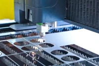
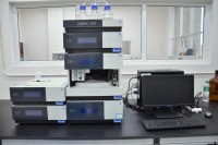
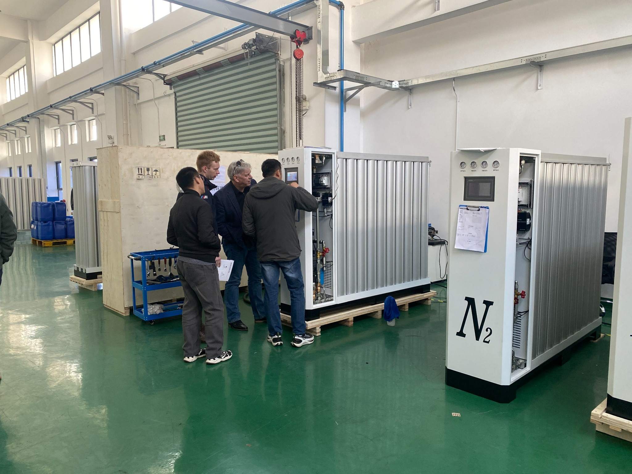
Customer Site Proof: Real Installations for Selective Wave Soldering
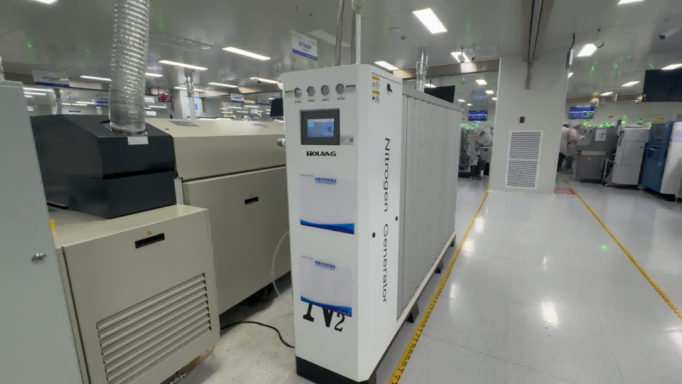
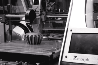
The photos in this article are real on-site cases. They reflect typical line-side conditions: limited floor space, clean workshop requirements, and the need to connect nitrogen supply reliably to selective soldering hoods or inerting zones. If your project involves multiple stations, expansions, or different product families, these real layouts are exactly what should guide system sizing and distribution planning.
Why Nitrogen Matters in Selective Wave Soldering
Selective wave soldering is sensitive to oxidation because the solder surface is hot, exposed, and continuously renewed. Oxygen reacts with molten solder to form oxides; these oxides interfere with wetting and can increase bridging, non-wetting, solder balls, and poor hole fill. Separately, oxidation forms dross (oxide-rich waste), which increases alloy consumption and creates more frequent pot cleaning. Nitrogen inerting reduces oxygen concentration around the soldering zone, lowering oxidation and stabilizing wetting behavior.
In practice, nitrogen is not a “quality luxury”—it is a controllable engineering lever that can improve repeatability, reduce material loss, and support better yield consistency across shifts. The key is not only reaching a target purity number, but maintaining stable oxygen ppm at the process point (the hood / soldering zone), even when the machine cycles, doors open, or production changes.
Typical Oxygen ppm Targets and What They Mean on the Floor
There is no single universal oxygen setpoint, because optimal targets depend on:
- Solder alloy (lead-free alloys generally oxidize more aggressively than SnPb)
- Flux chemistry and solids content
- PCB surface finish and solderability condition
- Hood design and enclosure leakage
- Process goals (dross reduction vs maximum wetting margin)
Many factories start with localized inerting at the solder module to reduce dross and improve wetting stability. If defects remain dominated by wetting-related modes (hole fill, non-wetting, bridging) or if product mix becomes more demanding, the project typically evolves toward tighter oxygen control and improved enclosure performance. The most important takeaway is this: oxygen ppm should be measured and validated where soldering happens, not only at the nitrogen generator outlet.
Flow Sizing: Selective Soldering Uses Less Gas, But Needs Consistency
Compared with full wave soldering, selective soldering normally requires lower nitrogen flow, but the supply must stay stable under real operating conditions:
- Purge demand at start-up or after maintenance
- Machine cycling and hood opening events
- Simultaneous operation of multiple pots/modules
- Distribution pressure drops (long runs, elbows, quick connectors)
A practical rule is to size nitrogen not only for average consumption, but also for peak purge events and future expansion. Undersizing often shows up as oxygen spikes and unstable wetting behavior—problems that are easily misdiagnosed as “flux issues” or “process tuning problems.”
Recommended System Architecture for Selective Wave Soldering
A robust nitrogen solution is a complete utility system, not a single box. For selective wave soldering lines, the most stable deployment typically includes:
- Compressed air source with stable pressure and sufficient capacity
- Drying & filtration to protect adsorption media and maintain nitrogen quality
- PSA nitrogen generation for continuous supply
- Buffer tank to stabilize demand fluctuations and purge events
- Regulation & monitoring close to the point of use
- Oxygen ppm verification at the hood / inerting zone
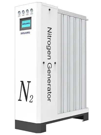
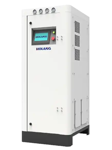
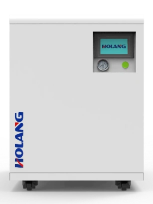
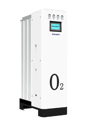
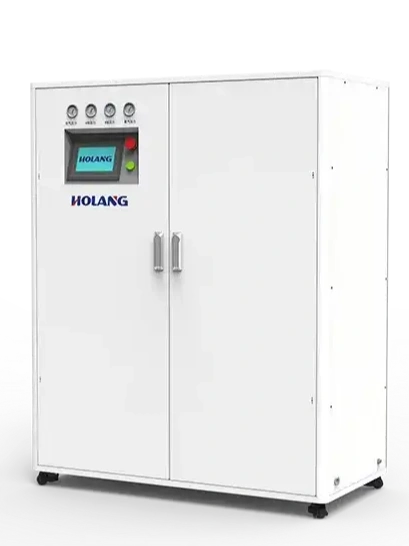
If you want a production-ready, line-scalable solution, the typical selection is an industrial PSA system such as the Industrial Nitrogen Generator. For small pilot lines, lab validation, or compact cells where compressed air may not be available at point-of-use, a more integrated approach like the Lab/Small Nitrogen Generator can be considered.
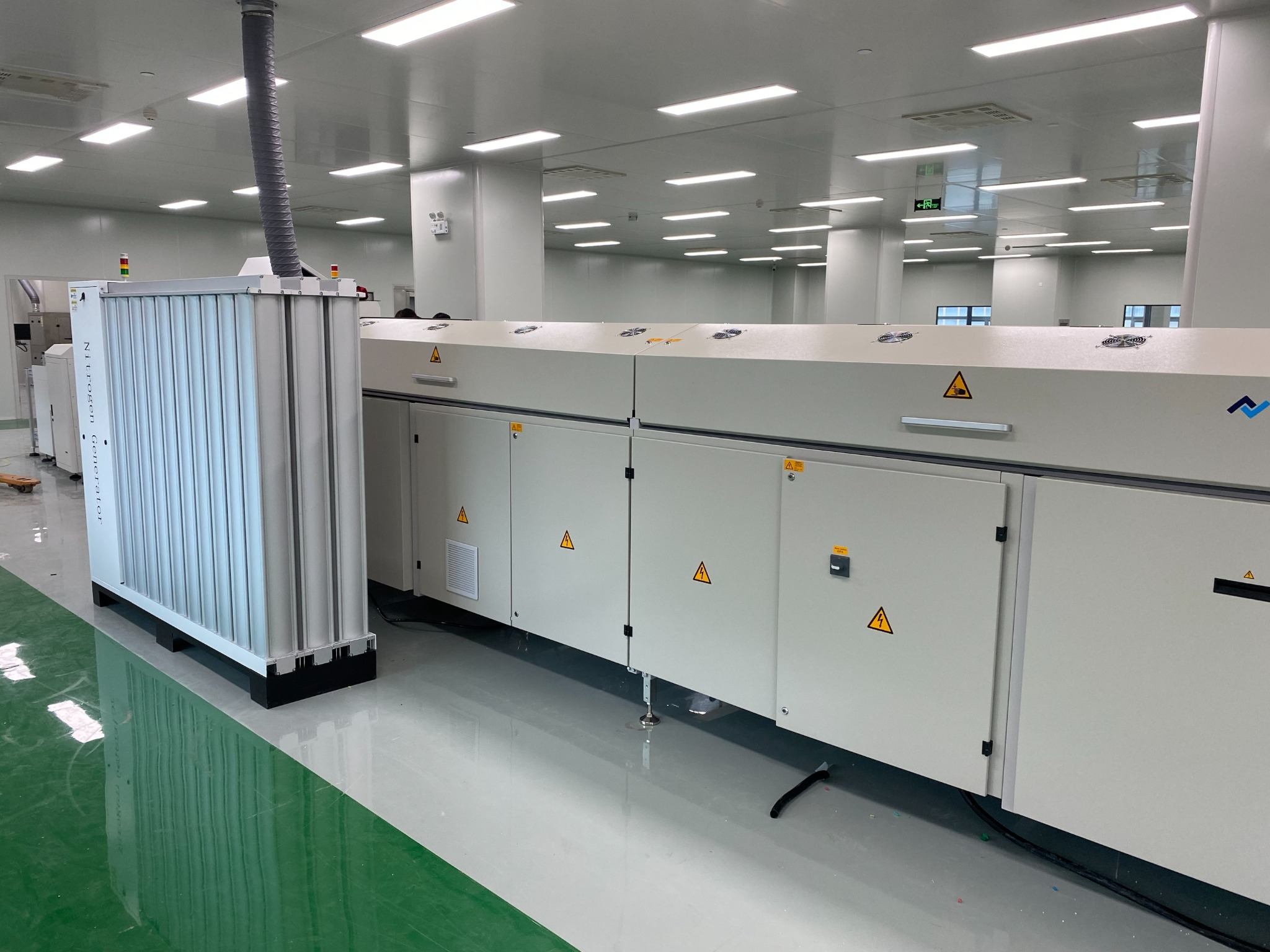
Real-World Layout: Line-Side Placement and Integration Details
Line-side placement is popular because it reduces pipe length, minimizes pressure drop, and improves maintenance access. The best layouts keep the nitrogen generator close enough to reduce loss, but far enough to maintain safe working clearance and service space. In selective soldering environments, good installation also emphasizes low vibration practices: stable mounting feet, properly supported piping, and secure cable/hose management. This helps maintain mechanical stability and avoids stress on fittings during long-term operation.
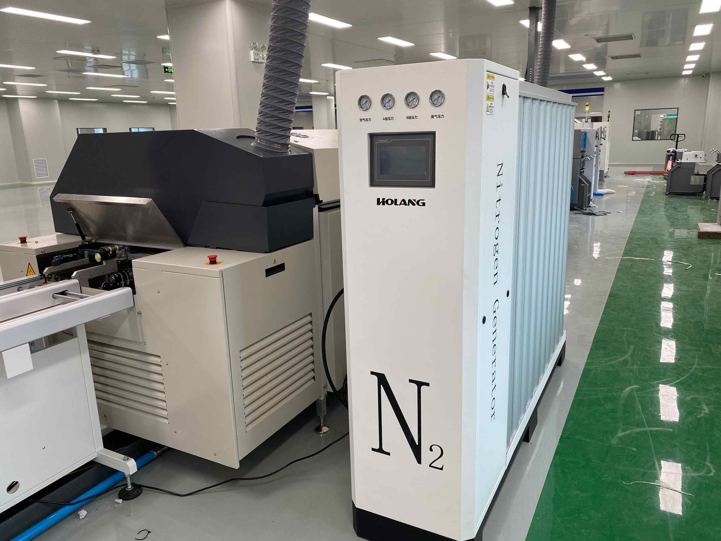
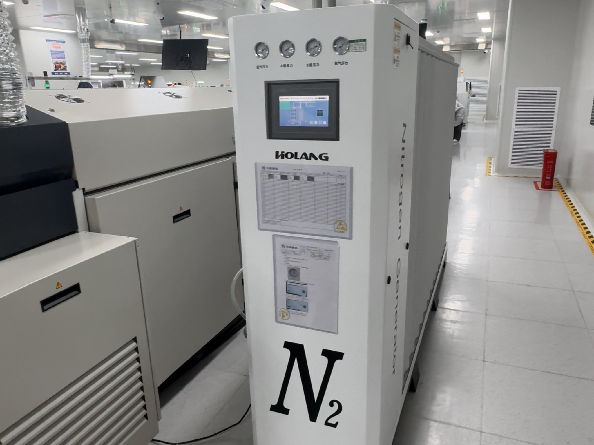
Front-Panel Controls: What Operators Actually Use
On the factory floor, operators care about stability and clarity: outlet pressure, purity indication, alarms, and quick diagnosis. A visible front-panel HMI and gauges simplify shift handover and reduce troubleshooting time. For selective wave soldering, this becomes especially valuable during:
- Start-up purge and stabilization
- Product changeovers
- Maintenance events on the solder module or hood
- Unexpected oxygen spikes caused by enclosure leakage
A practical best practice is to document the inerting setpoints and inspection items near the system (daily/weekly checks). This turns nitrogen from a “black box utility” into a controlled process variable.
Factory Deployment: Scalable Installations and Continuous Operation
Many selective wave soldering projects begin as a single line requirement and later expand: more pots, more stations, or additional inerting points. A scalable nitrogen supply plan reduces future rework. In expansion scenarios, planning typically includes:
- Reserve capacity for future demand
- Buffer tank sizing that can absorb purge peaks
- Distribution design for multiple take-off points
- Clear monitoring strategy (oxygen ppm validation at process points)
If your customers operate ERSA / ZSW / QUICK equipment with diverse product mix, stable nitrogen supply becomes an operational baseline rather than a one-time upgrade.
Commissioning, Acceptance, and Service: How to Build Customer Confidence
In B2B projects, trust is built during commissioning. A clean commissioning routine usually includes:
- Baseline measurement (current dross level, defect Pareto, rework time)
- Leak check and enclosure verification at the soldering hood
- Purge SOP for start-up and restart events
- Oxygen ppm stability test during real machine cycling
- Training for operators: what to check, what alarms mean, what “normal” looks like
For customers, this process turns nitrogen supply into a measurable improvement rather than a “marketing upgrade.” For integrators and service teams, it reduces warranty-style complaints and improves long-term satisfaction.
How to Prove ROI: Metrics That Management Understands
To justify nitrogen inerting for selective wave soldering (or to justify upgrades to tighter oxygen control), focus on metrics that directly link to cost and productivity:
- Dross mass per week (material loss indicator)
- Solder alloy consumption (direct cost)
- Defect Pareto (bridging, non-wetting, hole fill, solder balls)
- Rework hours (labor + throughput impact)
- Downtime from pot maintenance and cleaning
- Oxygen ppm stability (min/avg/max at hood during production)
A recommended approach is to record 2–4 weeks of baseline data before nitrogen deployment, then measure the same window after stabilization. This makes improvements visible and defensible, especially in EMS environments with frequent product changeovers.
Quick Configuration Checklist (Selective Wave Soldering)
- How many pots/modules today? How many in 12–24 months?
- Target oxygen ppm at the hood (define by defect mode and cost goals)
- Nitrogen flow requirement (include purge peaks, not only steady state)
- Compressed air quality (oil/water/particulates controlled)
- Buffer tank sizing to smooth cycling and purge events
- Pressure regulation near point-of-use to reduce variation
- Oxygen monitoring method (verify at the process point)
- Low vibration installation (stable mounting + supported piping)
- Commissioning SOP (leak check, purge routine, alarm thresholds, training)
Recommended Product Path
For production selective wave soldering lines requiring scalable and stable nitrogen supply, start with:
- Industrial Nitrogen Generator – for continuous factory supply and expansion-ready deployment.
For pilots, lab verification, small consumption points, or compact cells:
- Lab/Small Nitrogen Generator – for point-of-use supply where integrated architecture is preferred.